Hardware Configuration
In this section, we’ll describe out to get your PiFire system built out in hardware.
I Have a ___ Grill, Will it Work With PiFire?
Well, odds are, if you have an older Traeger or similar clone with all AC components (Auger, Fan, Igniter) and PT1000 temperature probe then PiFire could drop right in and work. If your grill is newer and has DC components, the answer is a little more nuanced. However, that doesn’t always mean that you are out of luck. Generally speaking you may be able to swap out certain components like the fan or igniter for off the shelf AC components that may work. It will just be a tiny bit more cost and effort.
Check out this Google spreadsheet here to see if your grill has been known to work with PiFire before. NOTE: This is a publicly editable spreadsheet, so please don’t delete any data from it.
Getting Started
The fastest way to get up and running is to utilize one of the PCB designs. There are several to choose from, having their individual strengths and use cases.
- 4.x.x PCB (and modules) - The state of the art currently is the 4.x.x PCB set which consists of a main board that connects to the Raspberry Pi (Connects to almost any Raspberry Pi model with 40 pin header). The main board must be paired up with a probe board (i.e. ADS1115 carrier board, or other probe device board(s)) as well as a relay/fan board. These boards are not as compact as the next board on this list, but has the most flexible/scalable options.
- Compact PWM PCB - Designed by user @weberbox, this compact board includes a power supply, relays, and PWM circuitry on-board. This board was designed to be utilized as an all-in-one unit that could be utilized with most installations, even portable smoker units! This board is compatible with Raspberry Pi Zero W/2W models, but needs pin headers to be soldered to the backside of the Pi Zero board. While compact, you will be limited on just the features included with this board.
- OSHWLab PCB w/DC Fan PWM Version: https://oshwlab.com/zipster85/pifire-controller-pwm-1.2
- Handy BOM List for the above PCB: https://github.com/nebhead/PiFire/files/9720705/PiFire-PWM-1.2-2022-BOM.xlsx
- 3.0.x, 2.0.x PCBs - Legacy PCB designs to be used with Raspberry Pi Zero W / 2W models. These PCB designs are no longer recommended, but are still perfectly usable.
- Custom Build - For the brave and curious, there is always the option to build your own from scratch as well, without using a PCB, which is described in Appendix-A: Legacy Hardware.
4.x.x PCB Details
The 4.x.x PCB is designed as a standard Raspberry Pi Hat that is compatible with most Raspberry Pi models including the Raspberry Pi Zero W/2W, Raspberry Pi 2/3/3a/3b/4/5. This hat will not work with the compute modules.
The PCB has mounting holes that fit standard stand-offs for the Raspberry Pi models mentioned above, such that the boards can be securely mounted together. This board also incorporates keepouts so that it can be used as a hat with most of the Raspberry Pi boards.
Some particular upgrades from previous revisions of the PCB:
- Some GPIOs have been re-assigned because they had conflicts with other functionality or had undesirable behavior on boot/shutdown (i.e. the TXD/RXD pins).
- This board removes the selector switch (used to select the OEM controller) and replaces it with an on/off power switch option using the native power on/off capability on the Raspberry Pi (i.e. graceful shutdown and power-up).
- This board does have an optional I2C EEPROM to store overlays. This is not currently implemented and should not be populated.
- There is an optional 12V input to pass through to the PWM Fan board.
- Two SPI headers are included with selectable chip enable pins and voltage levels. This allows the ability support two different SPI devices such as a display and a RTD probe reading chip.
- The 1-Wire interface has been added to support the DS18B20 reference probe.
- All un-used GPIO pins as well as power and ground pins are broken out into a separate header that can be used for miscellaneous options.
Links to the PCBs in the 4.x.x family of PiFire Boards
The 4.x.x Main Board PCB is part of a family of PCBs that can be used together to create a full PiFire system. Generally speaking you need the Main Module/Board, a Relay Control Board and a Probe Device board to have a basic PiFire system.
Click through the following links to see the board readme’s for more information about the designs, the interactive BOM lists (i.e. hardware needed), schematics, layouts, 3D-printable cases, etc. There are also instructions for ordering PCBs through JLCPCB, however you may be able to purchase these boards from others who may have extra boards on our Discord.
Main Module/Board (required)
Relay/Fan Control Boards (choose one)
- Mechanical Relay Module
- Solid State Relay Module
- Solid State Relay + PWM DC Fan Module - Original Design
- Solid State Relay + PWM DC Fan Module Alternate - Updated Design (Designed with help from @labmonkeyrat on Discord)
Probe Device Board (optional)
- ADS Board - This board can be chained with more ADS boards to ‘stack’ up to 16 probe inputs.
General 4.x.x PCB Architecture
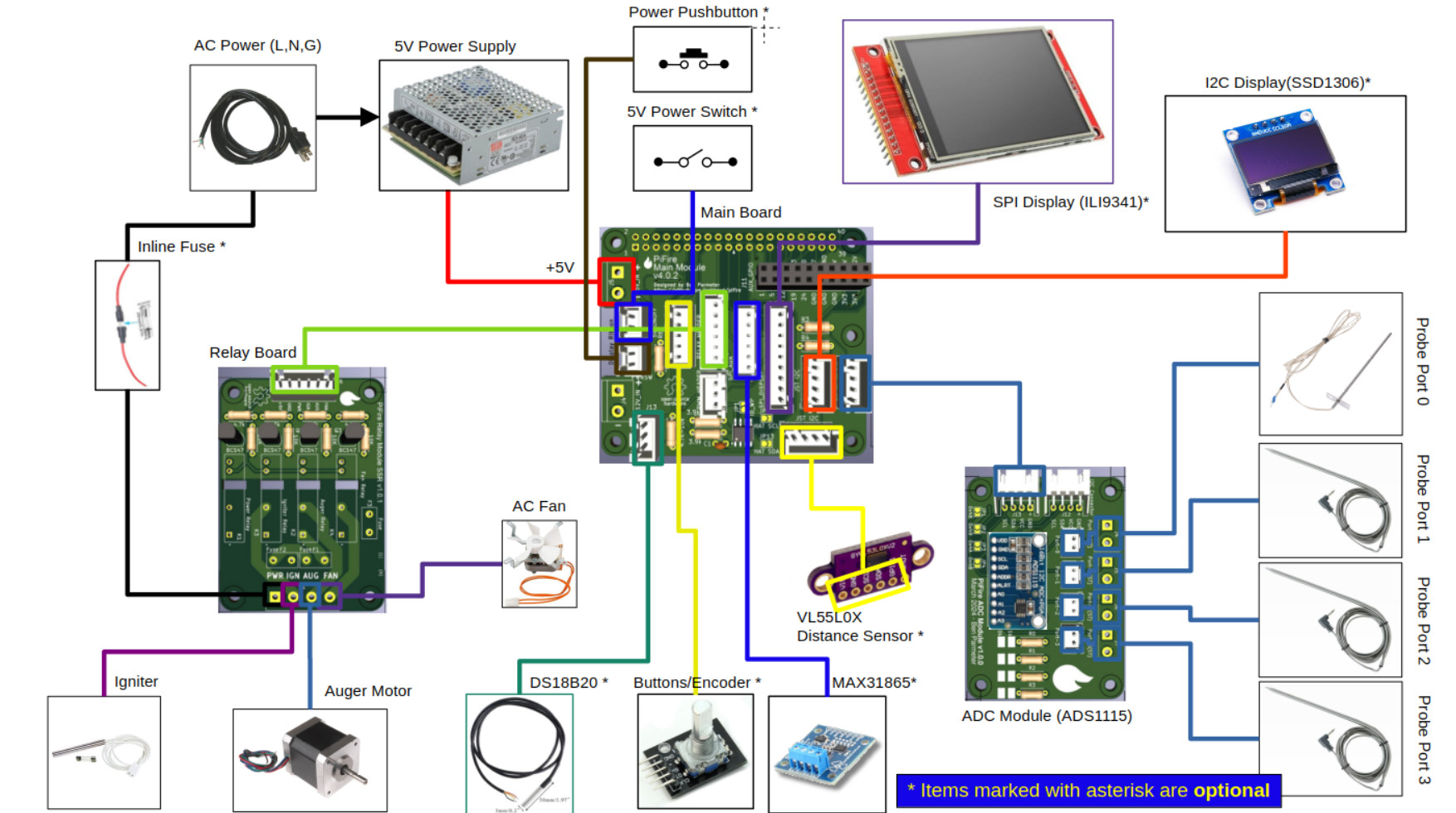
Sometimes it is easier to understand how a project is built out by looking at the general architecture. I’ve created a high-level diagram of the project so that you can get an idea of how all of this should be connected up.
The first diagram is of the AC Fan Version of the system. This version only requires a 5V power supply and only uses a portion of the headers to connect to a relay board. Technically speaking, in this configuration you could use an off the shelf relay board if you wanted to wire this up yourself.
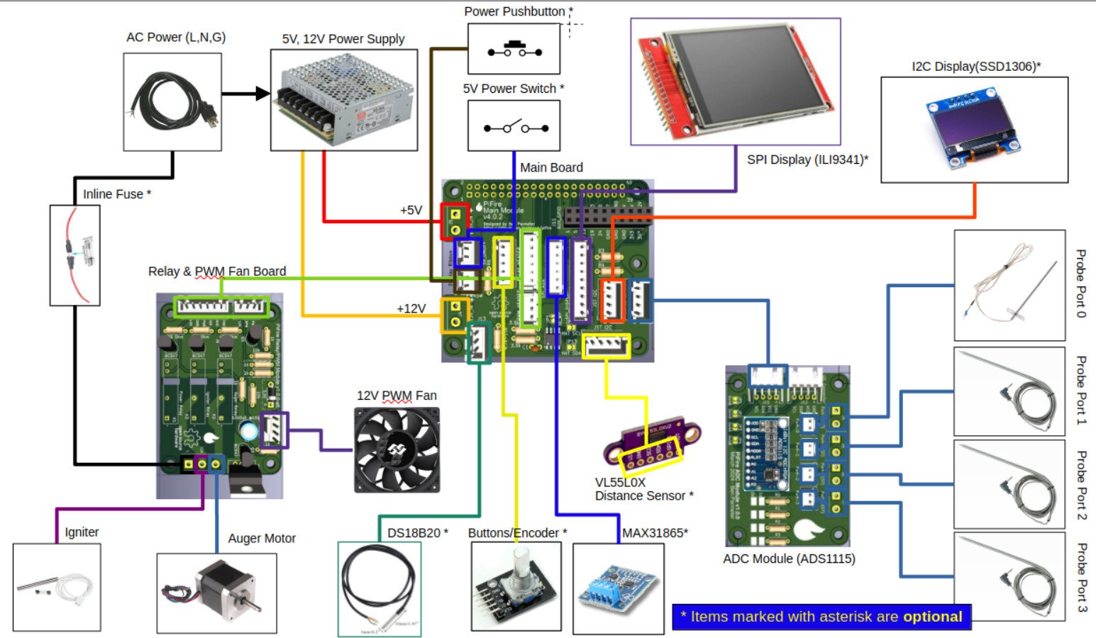
The second diagram is of the DC PWM Fan version of the system. You’ll notice that this version utilizes a 5V/12V power-supply and the specially design relay/PWM Fan board.
PCB 4.x.x Pinout
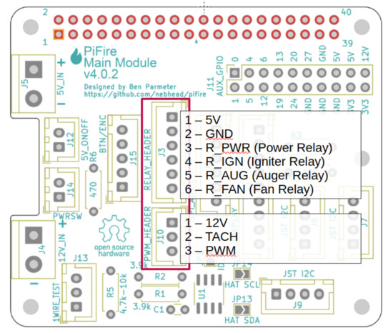
Due to space constraints on the PCB silkscreen layer, most of the pins for the JST connectors are unmarked. Thus I’m providing a handy set of images for the pinout of the major unmarked JST connectors.
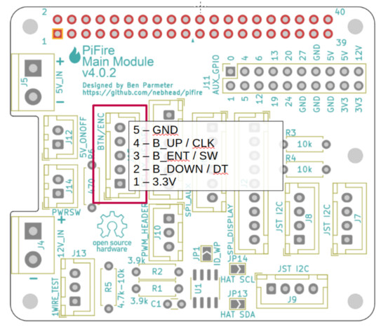
Buttons & Encoder Header
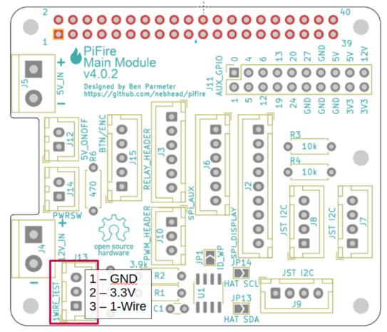
1-Wire Header - Used for the DS18B20 reference probe. Great for using as a reference to tune your other probes.
Relay and PWM Fan Headers - If you are not using the DC Fan, then only the top header needs to be populated.
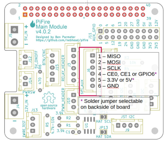
Auxiliary SPI Header - If you are already using the display SPI header, this can be used for another SPI based device such as the MAX38165 RTD probe device.
You must bridge solder jumpers on the back the board to select Chip Enable 0, Chip Enable 1 or GPIO6 (CE0/CE1/GPIO6) and 3.3V or 5V. Do not bridge both 3.3V and 5V or CE0 and CE1 at the same time or you may damage your system.
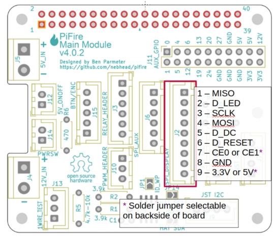
Display SPI Header - If you are using a SPI based display like the ILI9341, then this header should match the pinout for that display.
You must bridge solder jumpers on the back the board to select Chip Enable 0 or 1 (CE0/CE1) and 3.3V or 5V. Do not bridge both 3.3V and 5V or CE0 and CE1 at the same time or you may damage your system.
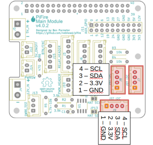
I2C Headers - All of the I2C headers pinouts are identical and can be used for any of the I2C devices including the ADC board, an I2C display, or an I2C distance device.
PCB 4.x.x Board Family DigiKey BOMs
User @StubbyTech on Discord has put together some DigiKey BOM files for some of the boards. I’ve not verified all of the parts in these lists, but it’s a great starting point to order parts if you don’t already have some of these on hand.
- Main Board: https://www.digikey.com/en/mylists/list/LLQX6AUZOU (Note that while the EEPROM is included, it is not required or used currently)
- Relay Module SSR: https://www.digikey.com/en/mylists/list/BZRJT3PQ1P
- ADS Board: https://www.digikey.com/en/mylists/list/1HC6VYPBZZ
Displays
PiFire doesn’t require a display to be attached, but it is a nice addition to have. The following are some supported options. These can be selected during the initial configuration wizard.
- SSD1306 - Standard 1” OLED display with I2C interface (64Hx128W). It’s pretty tiny, but it does the job and it can be found very cheap if you are willing to order direct from China. This is what was used for the initial/default implementation on the PiFire project. Make sure you get the all-white display and not the two-color (yellow/blue) display. Example linked below. (Raspberry Pi I2C Pin Mapping listed below)
- ILI9341 Based Display - Many versions of this display are available from different sources. I’ve built the ILI9341 support around the 240Hx320W SPI version of this. Note that there are currently some 4” versions of this display, but they have a larger resolution and are not currently supported. Also note that there are ‘V’ variants of the display which are also not currently supported.
- Amazon Link (Pin Mapping listed below)
- ST7789 Based Display - Again, many revisions of this are available from many different sources. Both a 240x240 and 320x240 screen resolution is currently supported. Also note that there are ‘V’ variants of the display which aren’t officially supported. However, there is an experimental library that you can try, which is available in the configuration wizard options.
- DSI Touch Display - Since the v1.7.0 release of PiFire, a DSI Touch based display has been introduced for the Raspberry Pi full sized board. Note that DSI is not supported by the Pi Zero or Pi Zero 2 boards. Note that performance may be slow when using this display due to the system requirements for displaying full screen graphics.
Physical Input
Some display types allow for physical inputs to control PiFire at the grill itself. Currently, either buttons or a rotary encoder are available as input options (aside from touchscreen controls on a DSI touch display).
Button Input
For Button Input, the following is an example of how tactile switches can be wired, with pullups. The 4.x.x PCB has the GPIO inputs exposed at a JST header. You’ll need to build or source a button board to be used with this design.
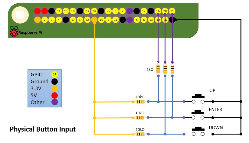
Pins Assigned for Button Input on the v4.x.x Board
- GND
- B_UP - GPIO 14 - Up Input Button
- B_ENT - GPIO 15 - Enter Input Button
- B_DOWN - GPIO 16 - Down Input Button
- 3.3V
See Button/Encoder header pinout above…
Popular switches for projects which can be obtained almost anywhere very cheaply. Here is an Amazon Link.
@weberbox has also created a very useful button board that can be used to simplify the button input. Note that this board is designed with active HIGH inputs and should be configured HIGH in your modules setup.
- EasyEda Button PCB: https://easyeda.com/zipster85/pifire-buttons
Rotary Encoder Input
Rotary encoders offer a simple alternative to implementing buttons. The KY040 encoder is supported by some display types with the below pin assignment on the 4.x.x PCB.
Pins Assigned for Rotary Encoder Input on the v4.x.x Board
- GND
- GPIO 14 - CLK (Clock) (Marked as B_UP on the PCB)
- GPIO 15 - SW (Switch) (Marked as B_ENT on the PCB)
- GPIO 16 - DT (Data) (Marked as B_DOWN on the PCB)
- 3.3V
See Button/Encoder header pinout above…
No additional board is needed as the pullups/pulldowns are already included on the KY040 boards. Amazon Link
Distance Sensors
PiFire supports a few options for distance sensors to detect pellet levels in the hopper.
- VL53L0X (RECOMMENDED) - Time of flight sensor with I2C interface. This sensor allows the ability to measure the hopper pellet level quite easily and reliably. While it can be a bit expensive on Amazon, this can be obtained from other vendors (directly from China) for relatively cheap. (Raspberry Pi I2C Pin Mapping listed below)
- HCSR04 - Ultrasonic Sensor with GPIO interface. This sensor hasn’t been tested, but the module support is provided for potential use/testing if desired. These sensors are cheap and ubiquitous.
Other Parts and Tools
Some other parts and tools that you may need for your build:
- Micro SD Card - 4GB or greater is required for Raspberry Pi OS Bullseye and later.
- 120V AC to 5VDC Power Supply - Generally speaking, getting a power supply with higher capacity (amperage) is recommended. For the standard build, a 5V 5A should work well. Power supply should be connected to the 5V input on the PiFire PCB (4.x.x). Do not connect the Raspberry Pi USB power input at the same time that this is connected.
- 120V AC to 5/12VDC Power Supply - If you are implementing the DC fan version of the build, you’ll want to get something that can output both 12V DC and 5V DC and has good headroom for amperage. Power supply should be connected to the 5V and 12V input on the PiFire PCB (4.x.x). Do not connect the Raspberry Pi USB power input at the same time that this is connected.
- Molex Connectors - To make life easier when plugging in standard components from your existing smoker, these connectors should make things easier. This basically allows you to easily plug into the existing connections on the smoker. I would highly recommend purchasing a ratcheting wire crimping tool, and watch some youtube videos to understand how these connectors work. Careful not to trim too much off of the leads so that they do not slide through the connector.
- 2.5mm Mono Audio Jack - I have finally found some very high quality 2.5mm jacks which can be found on ebay, Amazon and other Chinese electronics sites. These Philmore style jacks in either stereo or mono are excellent and very reliable. The catch is that they can be quite expensive. Up to $8 each in some cases. However, I feel this is worth the price compared to the cheap surface mount options out there. I have found that there are often better deals for these on ebay and Aliexpress. Search for Philmore. I recently picked up 10 mono versions of these jacks from ebay for $20 and they work really well.
- RTD1000 Traeger Temp Probe - For most builds, you may have an existing PT1000 temperature probe for the grill temperature. However if you are looking to replace it, then you will need one of these. Traeger calls these a PT100, but they are really PT1000 RTD probes where resistance is 1k Ohm at 0C. I’ll provide a link to Amazon here, but you can also order much cheaper versions of the same thing on Ebay.
- JST Connectors - You will need JST connectors, ribbon cable and a crimping tool. I’d recommend the following:
- AC Wire - For wiring up the AC components, it’s recommended to have at least 18 Gauge wire (16 Gauge is better) that is insulated and rated for higher temperatures. I like silicon insulated wire because it’s flexible and temperature resistant.
- DC Fan Options - If you plan to build the PWM fan version(s) of PiFire, there are a few known good options out there:
- Noctua NF-F12 iPPC 3000 RPM: Solid high quality PWM with reasonable airflow. Amazon
- Bgears b-BlasterPWM 5000 RPM: Very high airflow fan, which you may need to adjust in PiFire to reduce the maximum duty cycle. Plenty of headroom for adjusting. Amazon
- Iceberg Thermal IceGALE Xtra: High airflow fan which may have some cutout at lower duty cycles (less than 20%). Amazon
- DS18B20 - This probe type is connected to the 1-Wire interface and was primarily included to be an option for a reference probe. However, an astute user pointed out that many of these probe options are limited to 125C/257F which may not be sufficient for referencing/tuning the grill probe.
- DS18B20 Probes: Amazon
- MAX31865 RTD Sensor - SPI based RTD Sensor specifically tuned for the PT1000 probe. Very reliable, but only provides one sensor input and takes up one of the SPI options.
- ADS1115 - Popular I2C based 16bit Analog to Digital Converter. Note: Some have reported strange behavior with the ADS1115 module they have ordered from Amazon with this link. I ordered some additional ones from this link (on the West Coast of the USA) and they tested just fine. There is some speculation that some vendors are cutting corners and putting the cheaper ADS1015 on the board instead. If this is the case, you should be covered with the new modules added for the ADS1015 in the wizard.
- MCP9600 - K-Type thermocouple sensor board that works over I2C. This board is not recommended due it’s I2C speed limitations. You may find that you will need to reduce the I2C bus speed to utilize this board reliably.
- Bluetooth Probes - There are now several Bluetooth probes that are supported by PiFire. The following have been tested:
- Other Hardware? - I may have missed some items here, but check the specific PCB links above for the BOM (linked in the readme for each PCB) for other hardware items. PCB Links
User Builds
If you’re interested in seeing more builds from other users, we have a discussions thread here where others have posted pictures of their unique builds. In addition to the discussions thread above, the discord server is a great place to see and share build photos and experiences.