Hardware Configuration
The Parts List
The parts list and setup:
- Raspberry Pi Zero W - Technically any Raspberry Pi with WiFi will do fine, but for this application a Raspberry Pi Zero W works really well and is the right price. With the release of Raspberry Pi Zero W 2, this is an even better option for PiFire. The upgraded processing power really helps performance and is especially notably faster on boot-up.
- 4-Channel Relay - Needed for controlling all of the 120V outputs (Fan, Auger, Igniter, Power). The mechanical relay option may better suited for implementations where the existing controller is preserved, due to the NO, NC terminals are both available. If implementing a standalone, using a Solid State Relay is a great option. Take note of the trigger level for your relays as you will need to set this in the installation (default is active low level triggers).
- Resistors - (3x) 10k ohm resistors for grill RTD and meat probes resistor divider. You may want to consider getting some decent quality tolerance resistors for this given that accuracy is important(+/1 1%). I managed to source some pretty accurate dividers. It was mentioned on Discord by a user(James Cantrell), that using a smaller resistor value for the Primary RTD input (i.e. 1k) and configuring the profile to match this value might be a really good idea. This, in theory will give you higher accuracy on RTD probes which have a smaller resistance than the typical food probes. This is true for any PT1000 style probe, including some Pit Boss probes that have a similar resistance. (1x) 330 Ohm resistor for power selector switch. (3x) 10k Ohm resistors for optional physical button input, as well as (3x) 1k Ohm resistors.
- Micro SD Card - 4GB or greater is required for Raspberry Pi OS Buster and later.
- 120V AC to 5VDC Power Supply - In this particular case it's a 5V5A output which can be connected to the relay as well!
- ADS1115 - Popular I2C based 16bit Analog to Digital Converter. Note: Some have reported strange behavior with the ADS1115 module they have ordered from Amazon with this link. I ordered some additional ones from this link (on the West Coast of the USA) and they tested just fine. There is some speculation that some vendors are cutting corners and putting the cheaper ADS1015 on the board instead. If this is the case, you should be covered with the new modules added for the ADS1015 in the wizard.
- Molex Connectors - This is a super critical to making this a seamless integration of the controller. This basically allows you to easily plug into the existing connections on the smoker. I would highly recommend purchasing a wire crimping tool, and watch some youtube videos to understand how these connectors work. Careful not to trim too much off of the leads so that they do not slide through the connector.
- 2.5mm Mono Audio Jack - I have finally found some very high quality 2.5mm jacks which can be found on ebay, Amazon and other Chinese electronics sites. These Philmore style jacks in either stereo or mono are excellent and very reliable. The catch is that they can be quite expensive. Up to $8/piece. However, I feel this is worth the price compared to the cheap surface mount options out there. I have found that there are often better deals for these on ebay and aliexpress. Search for Philmore. I recently picked up 10 mono versions of these jacks from ebay for $20 and they work really well.
- RTD1000 Traeger Temp Probe - I decided to use a completely separate temperature probe for the actual pit temperature because I was too lazy to implement a solution to use the existing temperature probe. I'll provide a link to Amazon here, but you can also order much cheaper versions of the same thing on Ebay.
- Tack Switches - (3x) Optional for physical button input. Popular swtiches for projects which can be obtained almost anywhere very cheaply.
Display Options
PiFire doesn't require a display to be attached, but it is a nice addition to have.
- SSD1306 - Standard 1" OLED display with I2C interface (64Hx128W). It's pretty tiny, but it does the job and it can be found very cheap if you are willing to order direct from China. This is what was used for the initial/default implementation on the PiFire project. Make sure you get the all-white display and not the two-color (yellow/blue) display. Example linked below. (Raspberry Pi I2C Pin Mapping listed below)
- ILI9341 Based Display - Many versions of this display are available from different sources. I've built the ILI9341 support around the 240Hx320W SPI version of this.
- Amazon Link (Pin Mapping listed below)
- ST7789 Based Display - Again, many revisions of this are available from many different sources. The specific screen that I have built support on is from Waveshare, with a 240x240 screen and SPI interface.
Optional Hopper Sensors
- VL53L0X - Time of flight sensor with I2C interface. This sensor allows the ability to measure the hopper pellet level quite easily and reliably. While it can be a bit expensive on Amazon, this can be obtained from other vendors (directly from China) for relatively cheap. (Raspberry Pi I2C Pin Mapping listed below)
- HCSR04 - Ultrasonic Sensor with GPIO interface. This sensor hasn't been tested, but the module support is provided for potential use/testing if desired. These sensors are cheap and ubiquitous.
Hardware Schematics
Let me first say that I am not a hardware engineer by trade and thus there may be mistakes in what I'm providing here. I would encourage you to use this as a guide, but know that it isn't perfect by any means. Do let me know if there are any improvements that you can see for this.
UPDATE: There are now two design choices, with expanded support for displays as well. The original schematic is still applicable for anyone interested in leaving the existing controller in place alongside the PiFire controller. The newly added schematic is for a stand-alone configuration and also adds SPI screen support.
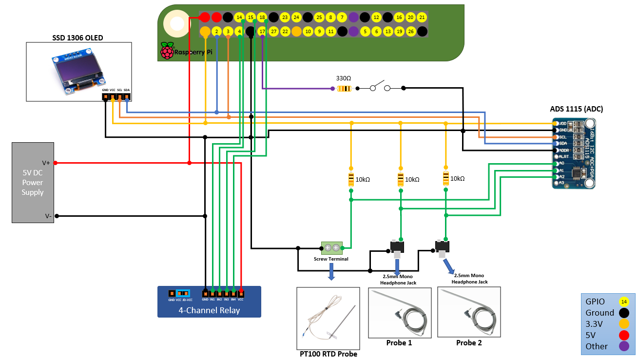
Example of basic PiFire wiring (PiSide) with SSD1306 OLED I2C based display.
If you are using a PT1000 (or Traeger PT100) RTD Probe, it has been pointed out (by Discord user James Cantrell) that using a 1k Ohm resistor would be a much better choice for that input channel instead of the 10k Ohm resistor. Since PT1000 probes are 1k Ohm at 0 degrees Celsius, this smaller 1k Ohm resistor divider is much more suited to give a wider range of voltage readings into the ADC. In future hardware designs, this should be something that is taken into consideration.
If you choose to change this to a 1k ohm resistor, you must remember to change the Rd value (Resistor Divider) in the Probe Profile that you are using.
It should also be noted that there are some food probes out there that use a similar PT1000 profile/resistor (i.e. Pit Boss). If you plan to use these types of probes, consider modifying the design for those channels to utilize 1k instead of 10k ohm resistor dividers.
There have been questions around the optional switch attached to GPIO17. This is only used in configurations where you are using both the original controller and the PiFire controller on the same grill. If you selected standalone during the wizard configuration, then this switch is ignored. If you selected OEM Controller Present in the wizard configuration, then this switch will control whether PiFire is actively controlling the grill, or the OEM controller is controlling the grill. This could potentially used to switch between the controllers on the fly, but is generally not recommended.
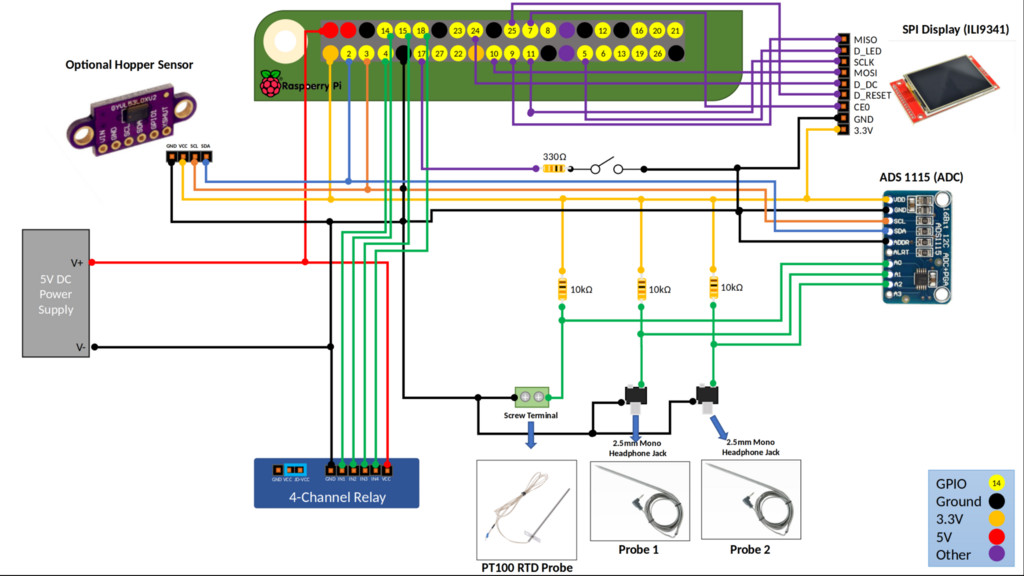
Example of advanced PiFire wiring (PiSide) with ILI9341 TFT SPI based display and VL53L0X hopper sensor.
PCB Design
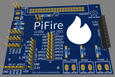
There is a PCB design which greatly reduces the wiring effort required for wiring up most of the devices. This new design is somewhat of a hat, in that can be plugged directly into the Pi Zero W header, and then breaks out the needed interfaces including I2C, SPI, ADS1115 and probe screw terminals. using the PCB isn't required, however it will make building this project much easier.
- The schematic, PCB and gerber files are available here: https://easyeda.com/nebhead77/pifire-v2
You can order your own directly from one of the many PCB manufacturers (very cheaply) or directly through JLCPCB. Unfortunately ordering from EasyEDA and JLCPCB is not very intuitive. Instructions to order through EasyEDA and JLCPCB were discussed in the following posting here.
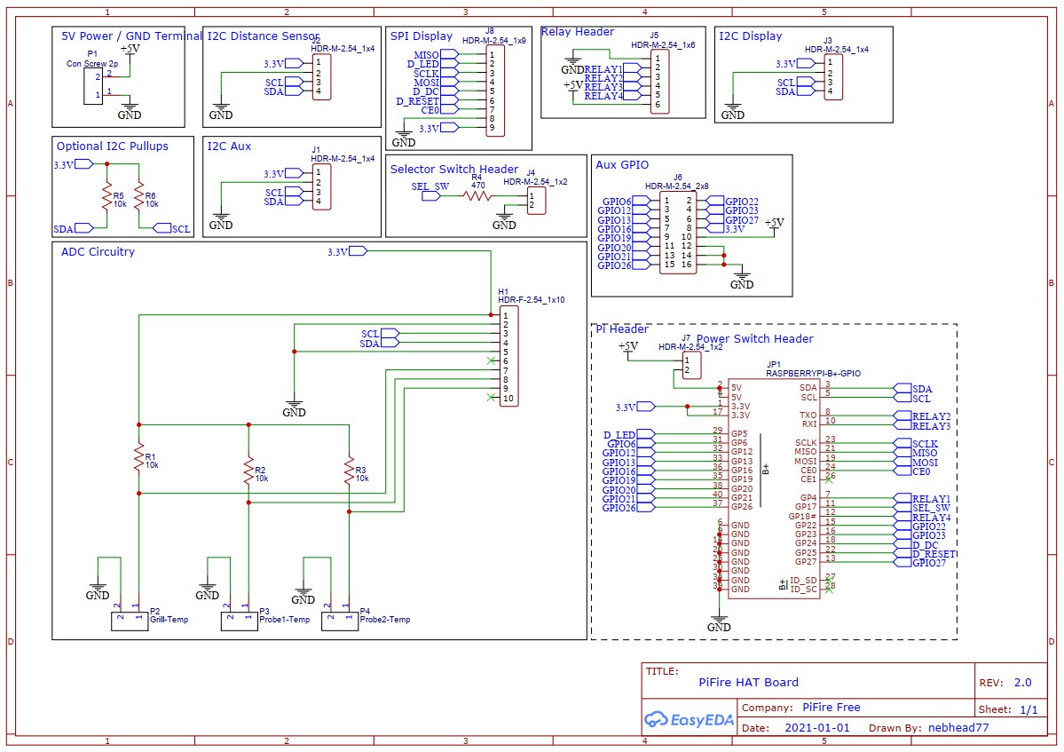
This PCB allows you to plug the ADS1115 into the header on the right side of the board with no additional wiring.
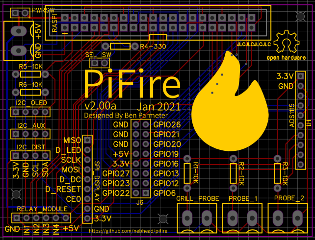
Here's a 3D-View of the board.
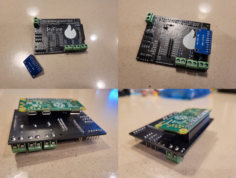
And here's a montage of the real thing all built out.
Other PCB Design Options
Github user @weberbox has extended the above design to add some other features, such as breaking out the fourth ADC input.
- EasyEda 4 Probe PCB Version: https://easyeda.com/zipster85/pifire-controller-hat
@weberbox has also created a very useful button board that can be used to simplify the button input. Note that this board is designed with active HIGH inputs and should be configured HIGH in your modules setup.
- EasyEda Button PCB: https://easyeda.com/zipster85/pifire-buttons
Update(2022-10-5):
Github user @weberbox has outdone himself again and created a very compact PCB for PiFire, with an integrated power-supply, Solid State Relays and 12V DC Fan with PWM support. This board isn't for everyone, but I personally think it's outstanding. Keep in mind that the Pi Header is reversed from ‘typical' configurations, so you may need to solder your header to the backside of the Pi, or convert with a cable/connector.
-
OSHWLab PCB w/DC Fan PWM Version: https://oshwlab.com/zipster85/pifire-controller-pwm-1.2
-
Handy BOM List for the above PCB: https://github.com/nebhead/PiFire/files/9720705/PiFire-PWM-1.2-2022-BOM.xlsx
AC Components & Relay Schematic
The following is a rough schematic of the relay side of the of the design. Basically this is what allows you to control the Fan, Auger, Igniter and Power as well as switch between the existing controller and the PiFire controller via software.
Note that wire colors may vary with different models of grills. I've tried to use the standard wire colors here that you may actually see, but if you've swapped out any components or have a newer/older version they may be different.
Figure A: PiFire w/Existing Controller 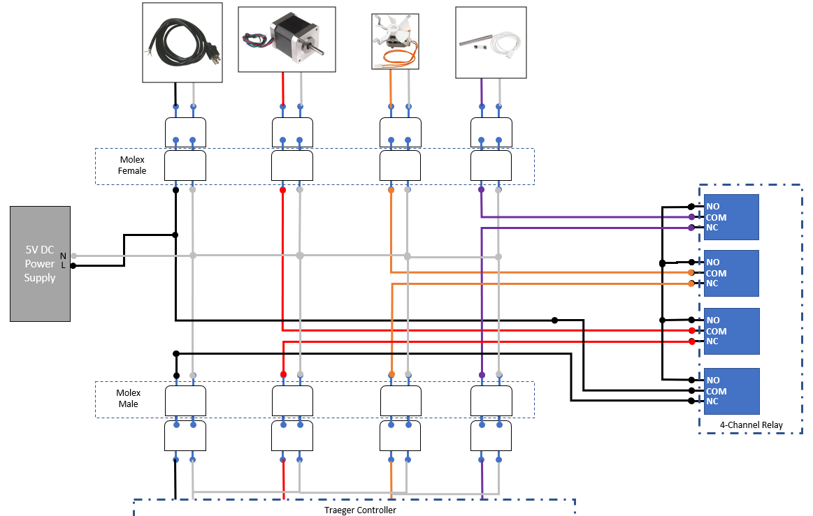
Figure B: PiFire Standalone 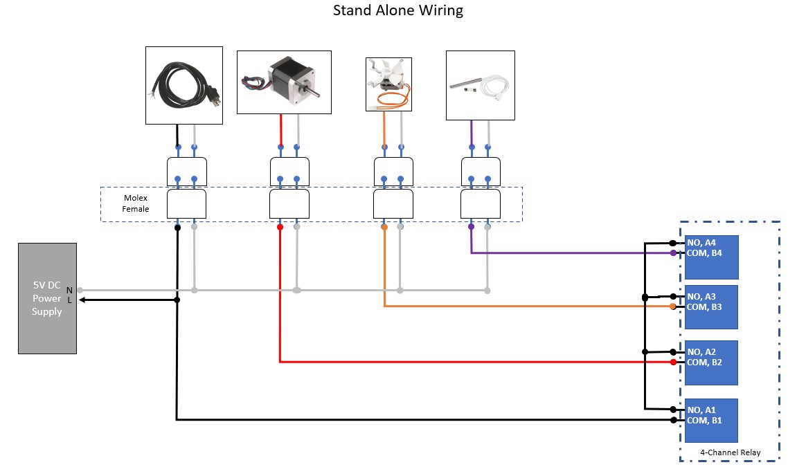
In the above figures A&B, the 5V DC Power Supply is show with Neutral and Hot(L) inputs. AC power should not be connected to the DC outputs of this power supply, or it may experience damage.
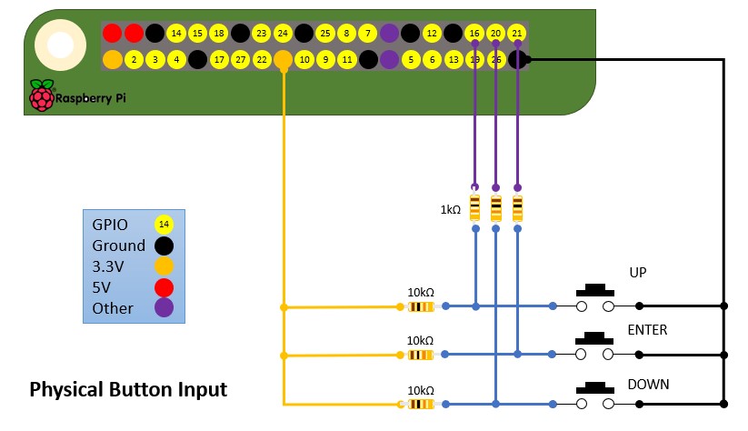
Physical Button Input
For Physical Button Input, the following is an example of how tactile switches can be wired, with pullups.
@weberbox has also created a very useful button board that can be used to simplify the button input. Note that this board is designed with active HIGH inputs and should be configured HIGH in your modules setup.
- EasyEda Button PCB: https://easyeda.com/zipster85/pifire-buttons
Raspberry Pi GPIO / PIN Mapping
Relay Control (defined in settings.json):
- GPIO 4 - Power (controls power to the outputs, between the existing controller and the PiFire controller)
- GPIO 14 - Auger Relay - Controls the Auger on/off.
- GPIO 15 - Fan Relay - Controls Fan on/off.
- GPIO 18 - Igniter Relay - Controls Igniter on/off.
#####Switch Input (defined in settings.json):
- GPIO 17 - Switch Input for system on/off
Button Input (defined in settings.json modules):
- GPIO 16 - Up Input Button
- GPIO 20 - Down Input Button
- GPIO 21 - Enter Input Button
- 3.3V - Any 3.3V rail pin
- GND - Any ground pin
Rotary Encoder Input (defined in settings.json modules):
- GPIO 16 - CLK (Clock)
- GPIO 20 - DT (Data)
- GPIO 21 - SW (Switch)
- 3.3V - Any 3.3V rail pin
- GND - Any ground pin
SPI Display Pins (ILI9341, etc.):
- Board Pin 21 - MISO
- GPIO 5 - LED
- Board Pin 23 - SCK (SCLK)
- Board Pin 19 - MOSI
- GPIO 24 - DC
- GPIO 25 - RST (Reset)
- Board Pin 24 - CS (Chip Select, AKA Chip Enable or CE0)
- Vcc - This should be 3.3V, however, some have noted that the ILI9341 are 5V tolerant and have a brighter display when connected to 5V. YMMV, so proceed with caution.
- GND - Any ground pin
I2C Pins (SSD1306, VL):
- Board Pin 3 - SDA
- Board Pin 5 - SCL
- 3.3V - Any 3.3V rail pin
- GND - Any ground pin
The Hardware in Pictures
Sometimes it's helpful to see the entire project laid out in picture form, so I've tried to put together some helpful pictures. As this project is evolving, so too has the hardware build out. I will keep the older hardware build here for posterity, but the newer version has updated much of the build to include many 3D printed parts.
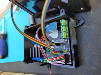
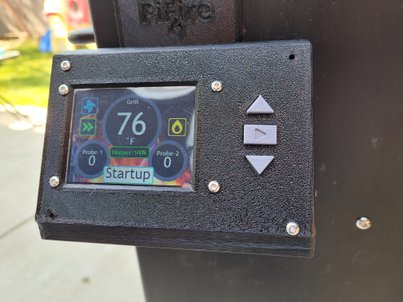
Current Implementation
The latest implementation improves upon the original design by utilizing a 3D printed enclosure for the display and control boxes (note is highly recommend to use PETG for it's temperature resistance). This implementation removes the existing controller and completely replaces it.
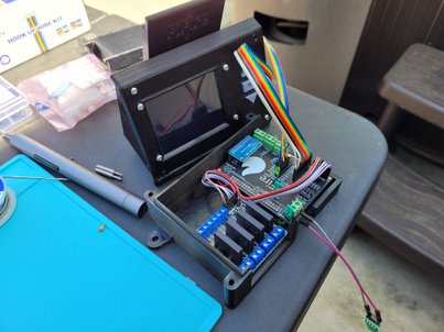
The below shows the display shortly after mounting on the grill (some screws still missing still - oops!).
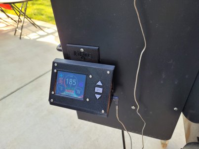
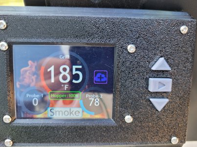
With a food probe attached:
If you’re interested in seeing more builds from other users, we have a discussions thread here where others have posted pictures of their unique builds. In addition to the discussions thread above, the discord server is a great place to see and share build photos and experiences.
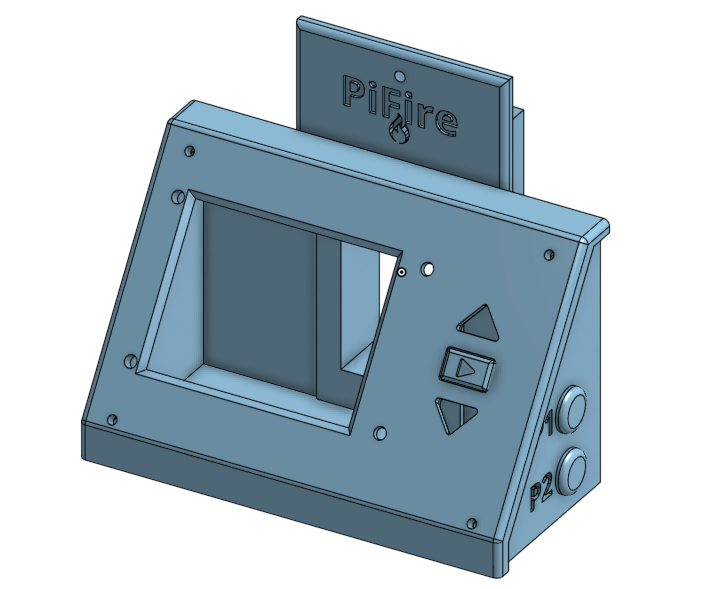
3D Printer Files
If you'd like to 3D print an enclosure, there are few options to choose from, but the main source files have been provided for a panel with ili9341 display and standard button input. It's highly recommended to print this design in PETG for it's heat resistant propperties.
The source design was done in OnShape and is based on the Traeger Texas Grill and can be found here:
This design can be cloned and modified to suit your needs if you are using on a different smoker.
STLs for this design can be found on Thingiverse here:
Other 3D Printable Resources
@weberbox has also created designs for a PitBoss FB700 but could probably be used on other grills. The OnShape links are also provided so the designs can be modified to suite specific needs.
-
Display Box Thingiverse: https://www.thingiverse.com/thing:5139144
-
Display Box OnShape: https://cad.onshape.com/documents/7c30dabaf483914d5d0ea10d/w/34b11bc17b55cc9ec2cbd3f8/e/681017a897d266fa8a7bcd75?renderMode=0&uiState=61945d0df20f441b9e619841
-
Control Box Thingiverse: https://www.thingiverse.com/thing:5139175
-
Control Box OnShape: https://cad.onshape.com/documents/5e8e29627182ca9be4d6c313/w/8144537579abfcb512d691ce/e/f9ef421aba3cd2a53878154b?renderMode=0&uiState=619465dd0781005a1b58ebcc
-
Auger Spacer OnShape (I needed this as my auger fan started to touch the control box) stl is with the control box on thingiverse: https://cad.onshape.com/documents/d1e81c5851a054343906a9ee/w/4cf9d91b67db4df4ce6475d6/e/35123253e2bf21c487d6c4cd?renderMode=0&uiState=619467e3b333ee4deac2a02a
-
Distance Sensor Thingiverse: https://www.thingiverse.com/thing:5139180
-
Distance Sensor OnShape: https://cad.onshape.com/documents/b95282d5ebd233bf22c48187/w/867e1e2e2f53551dd2575f1a/e/eaa8a945102367392b414161?renderMode=0&uiState=619467293958f85a7b286a18
@M7Fa has created a design for the PitBoss Austin XL and shared on Thingiverse.
- Display Panel Thingiverse: https://www.thingiverse.com/thing:5377280
Older Implementation
This section is provided for historical purposes. The design has evolved since the first iteration and this version is no longer being used. However, it might be useful to someone who is using PiFire alongside their existing controller or doesn’t have a 3D printer at their disposal.
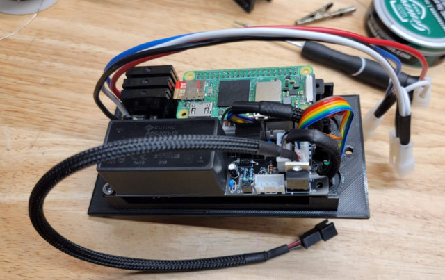
Here's a diagram showing all of the major components in the project box and how I laid them out. Certainly, you can do this differently but this was how I did it. Much hot glue and electrical tape was used. Please don't judge.
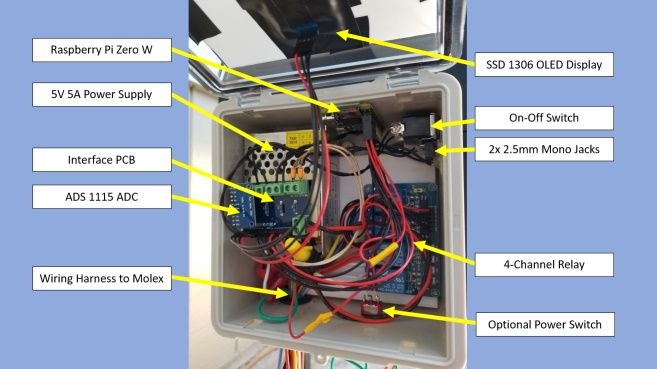
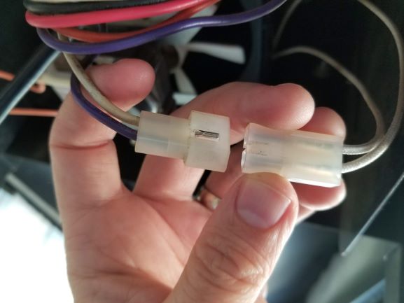
I'm not sure about other brands, but Traeger designed their Texas grills with handy Molex connectors for everything that hooks up to their controller. It makes the electronics underneath extremely serviceable and allows us to rather seamlessly connect our project in between.
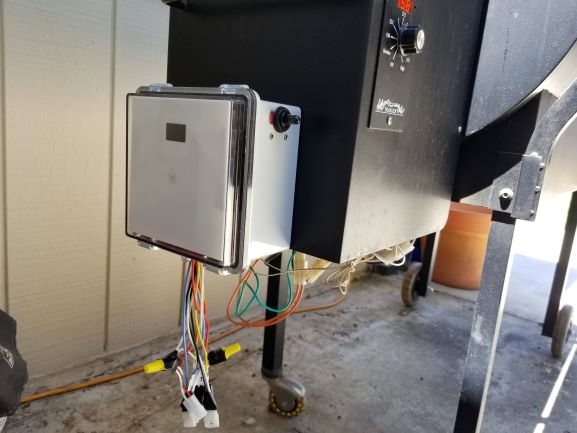
The following is a picture of the project from the outside. You can see that the OLED is mounted to the front of the box which has a clear lid. I put a piece of white plastic in the front to hide the electronics inside. The wiring with the molex connectors is fed through the bottom of the box to underneath smoker pellet box where all of the connections can be made. I've zip-tied the wires together, tucked them up in side the pellet box area, and made it nice and tidy.
On the bottom of the project box, I have drilled decent sized hole and installed a rubber grommet (to protect the wires) for all of the 18AWG wiring to be routed through. There are quite a few wires coming out, so it's good to give yourself some space, but maybe not too much given that your grill may exposed to the elements outside. It should be snug.
I also have an optional power switch down here, that is a normally closed momentary switch. This wired between the 5V power supply and the Raspberry Pi so that I can do a hard power-cycle when necessary. Or if the Raspberry Pi is off, a power cycle will boot it up again.
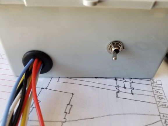
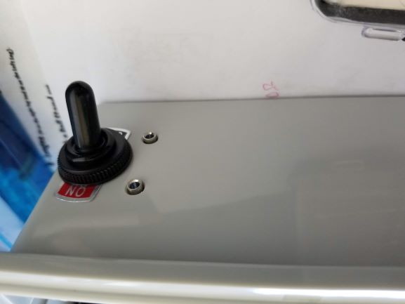
Around to the side facing the user (in my configuration), you'll see we have rather large selector switch which is used to select whether you are using the original controller (OFF) or the PiFire controller (ON).
Below this, are two 2.5mm mono jacks for plugging in your two meat probes. These were a bit fiddley to install, but I managed to hotglue them in place on the inside - and they feel really solid. EDIT: I've removed the hotglue for the 2.5mm mono jacks and replaced it with copious amounts of superglue. With temperatures rising above 100F here in Northern California, the hot glue softened too much to be mechanically sound. Some day I might have to come up with another solution, but for now, super-glue is doing the trick.
And if you're interested in seeing more builds from other users, we have a discussions thread here where others have posted pictures of their unique builds.